Inventing a Valve
Accompanying paper: A Novel Rotary Pinch Valve Design for Precision Control of Isolated High-Pressure Fluids (TechRxiv Preprint, 2025)
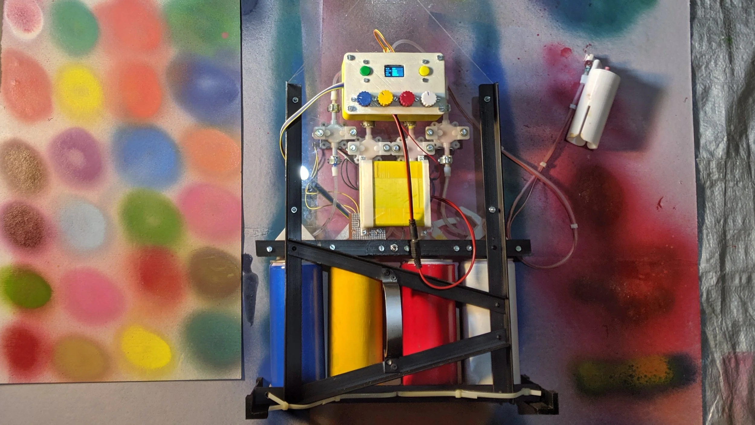
Spectrum, a breakthrough multicolor spray paint machine
I built a multicolor spray paint machine called "Spectrum" that can create any spray paint color instantly—you can read an article on it here. Spectrum works by rapidly pulsing tiny, precise amounts of primary paint colors into a mixing tube. This required electronic valves that could handle spray paint's high pressure, dose with millisecond precision, and prevent paint from clogging the mechanism.
No off-the-shelf valve could do all of this affordably, so I designed a new valve: the "Rotary Pinch Valve."
Valve Design Requirements
Isolated Fluid Pathway: Keep paint completely separate from the valve mechanism to prevent clogging.
Normally Closed: Default to closed when unpowered, so no leaks if power fails.
Total Back-flow Prevention: Stop back-flow even with no inlet pressure—essential to prevent massive leaks if cans get disconnected.
Fast Response: Have a response time of under 30 milliseconds for rapid pulse control.
Pressure Handling: Withstand spray paint pressure (up to 100 psi) with safety margin.
Inexpensive and DIY-Friendly: Built from inexpensive, readily available parts.
Design Overview: the Rotary-Pinch Valve
The concept is elegantly simple: a motor-driven lever pinches a flexible tube to control paint flow. While pinch valves exist, I needed one that was electronically controlled, normally closed, and fast enough for rapid pulsing. So I designed one from scratch, optimizing it for Spectrum.

Rotary-Pinch Valve: Basic Mechanism
How it Works without Clogging
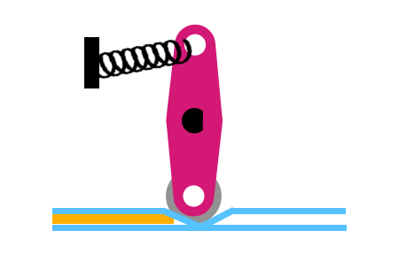
A rotating lever pinches flexible silicone tubing against a wall to stop paint flow. A bearing at the lever's tip prevents wear as it rolls over the tube. When the lever rotates down, it pinches closed; rotating back releases the flow. The paint stays inside the tube and never touches the mechanism—no clogging.
No Back-flow
When the lever is fully closed, fluid pressure acts perpendicular to the lever arm, creating no rotational force. This means no back-flow even with high outlet pressure—the valve stays firmly closed regardless of pressure differences.
Motor-Powered
The lever is rotated by a motor. I found stepper motors to be perfect for this valve—they provide precise positioning without needing position sensors, which keeps the logic simple. They also had sufficient torque and speed for rapid valve actuation.
Normally Closed with a Spring
A spring pulls the lever into its closed position when the motor is unpowered, ensuring the valve stays shut by default.
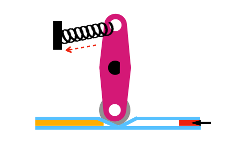
Spring holds the lever back by default, making the valve normally closed.
Rotary-Pinch valve mechanism with a spring for a normally-closed design.
Valve-Closed Position Feedback
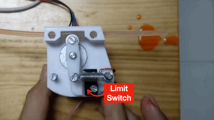
Limit switch for closing-feedback
I integrated a limit switch that the lever activates when fully closed. It tells the controller that the valve has successfully closed, providing position feedback for safe operation. This safety feature is important—if a valve fails to close when commanded, the system can immediately alert the user and shut off paint intake to prevent uncontrolled paint leaks.
While not required for basic single-valve operation, this feedback mechanism becomes essential for reliable multi-valve coordination and extended use.
The Math
The motor had to be fast enough while having enough torque to pinch the tube against paint pressure. The spring needed to reliably close the valve when unpowered, but not overpower the motor.
The detailed calculations for the motor and spring specifications can be found in the accompanying paper: A Novel Rotary Pinch Valve Design for Precision Control of Isolated High-Pressure Fluids (TechRxiv Preprint, 2025) . This section gives you an overview of the math without any boring equations.
The Tube-Pinching Reaction Force
When the lever pinches the tube, the tube exerts a perpendicular reaction force on the lever. Both the motor and spring must overcome this force, so knowing its magnitude at different pinch positions is critical for design.
Calculating this force using FEA or closed-form equations would be inaccurate due to the complex, nonlinear deformation behavior of silicone tubes under compression. Instead, I measured it experimentally.
The Setup: I tied a string to the lever and connected it to a spring balance scale via a pulley. As I rotated the lever through its range of motion, the spring balance measured the force required at each angular position. This gave me an experimental curve of tube reaction force versus lever angle.
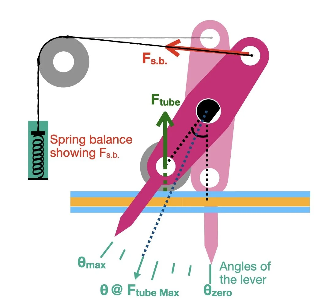
Setup Diagram
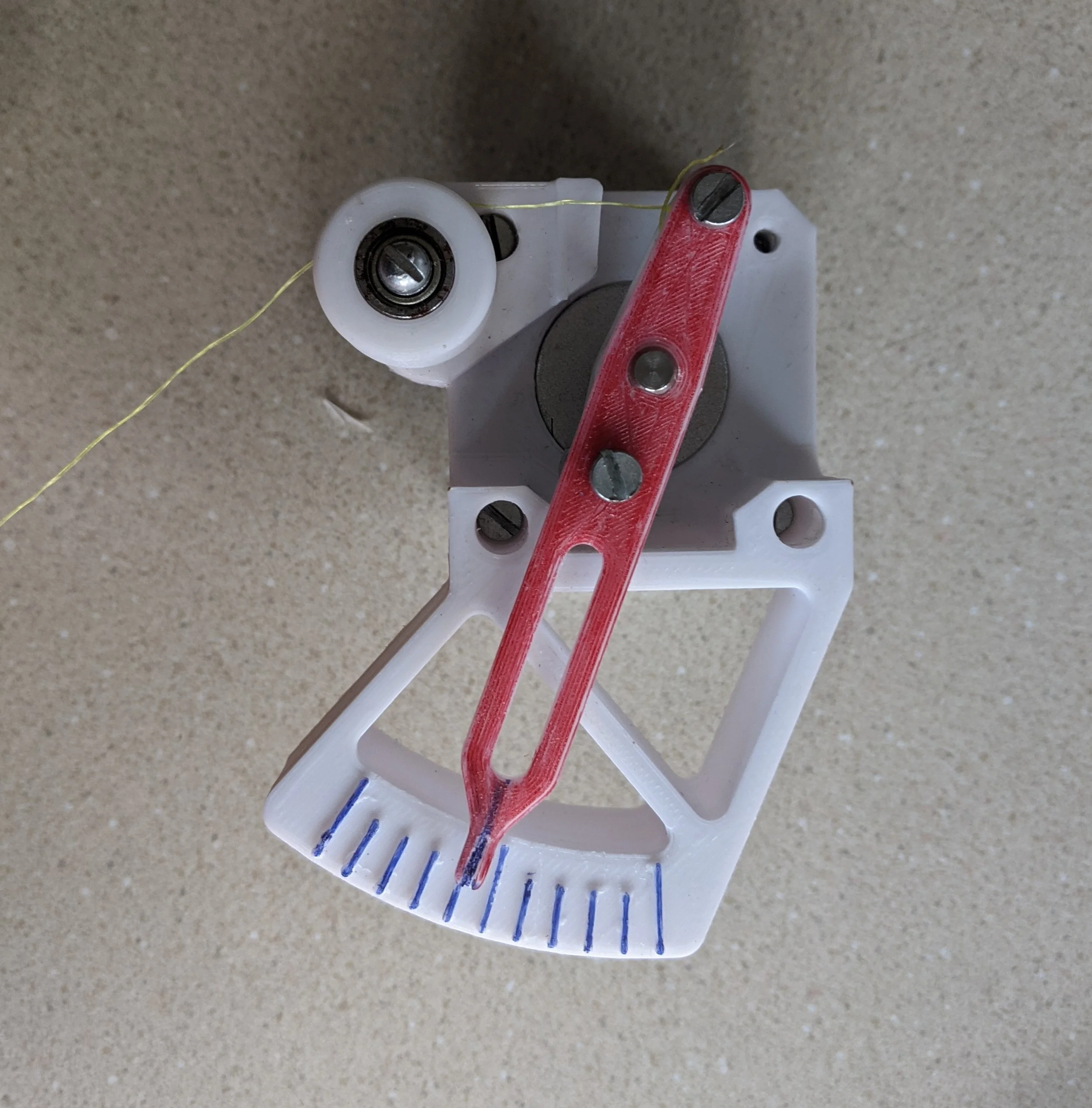
Actual 3-D printed setup
The tube reaction force varies significantly with lever position. When the tube is nearly fully pinched, the reaction force acts almost parallel to the lever arm, creating minimal torque. When the tube is barely pinched, the force itself is small since there's little compression. Somewhere in between these extremes, the combination of force magnitude and lever geometry produces maximum torque—this peak torque determines the motor and spring requirements.
Calculating Motor and Spring Specifications
The fundamental requirements are straightforward: the motor and spring together must overcome the tube's reaction force when closing the valve, and the motor must overcome the spring force when opening the valve.
With the experimental tube reaction force profile, you can calculate three critical specifications:
Motor Closing Torque - sufficient to compress the tube against its reaction force
Spring Closing Torque - sufficient to close the valve when the motor is unpowered
Motor Opening Torque - sufficient to overcome the spring force when opening
These calculations depend on design parameters like lever arm length, bearing position, and spring mounting geometry, all detailed in the accompanying paper.
The Future
This article focuses on the custom rotary pinch valve I developed for Spectrum, but there's plenty of room for improvement and deeper analysis. Here are some examples, if someone wants to take it forward:
Engineering Analysis:
Fatigue Analysis: How long do the structural components last under repeated cycling and what's the weakest point of failure
Theoretical modeling to approximate the tube reaction force without experimental measurement
Performance analysis for different tube materials and dimensions
Design Improvements:
A motor-to-lever coupling mechanism that doesn’t require reversing the motor’s rotational direction and could reduce power consumption during continuous operation
Environmental protection for harsh operating conditions by sealing the mechanism better
Optimization of geometry for improved response time
Control Enhancements:
Enhanced feedback control algorithms for faster response times and multivalve coordination
Integration with industrial control systems
This valve was built for my spray paint machine where traditional/existing valves failed or where too expensive. It not only works great, it costs less than $25 to build it yourself with 3-D printing. I am excited to see where else could this valve be used.